- 您现在的位置:买卖IC网 > Sheet目录331 > IR2011PBF (International Rectifier)IC DRIVER HIGH/LOW SIDE 8-DIP
IR2011(S) & (PbF)
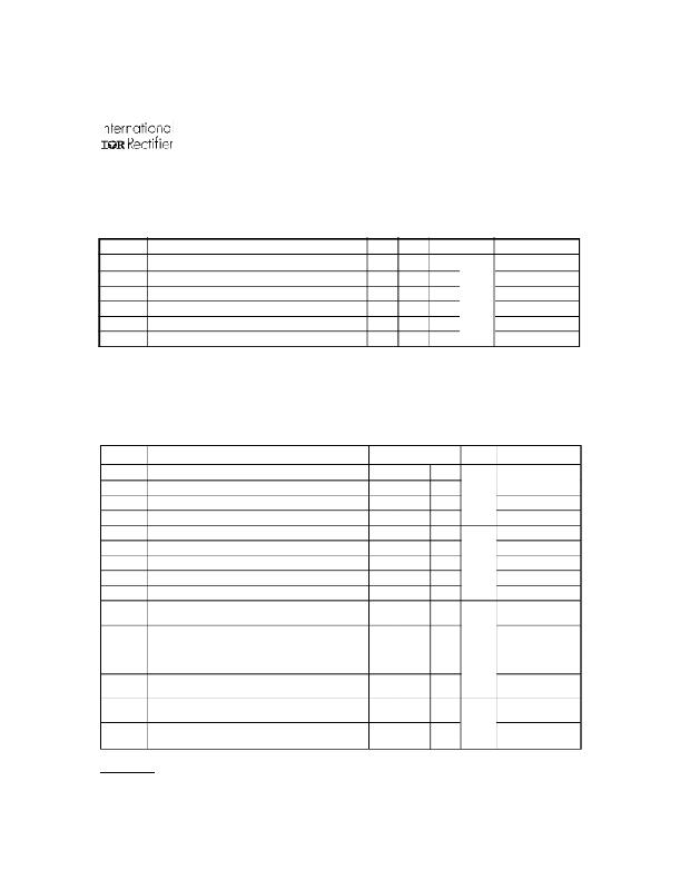
Dynamic Electrical Characteristics
V BIAS (V CC , V BS ) = 15V, C L = 1000 pF, T A = 25 ° C unless otherwise specified. Figure 1 shows the timing definitions.
Symbol
Definition
Min. Typ. Max. Units Test Conditions
t on
t off
t r
t f
DM1
DM2
Turn-on propagation delay
Turn-off propagation delay
Turn-on rise time
Turn-off fall time
Turn-on delay matching | t on (H) - t on (L) |
Turn-off delay matching | t off (H) - t off (L) |
—
—
—
—
—
—
80
75
35
20
—
—
—
—
50
35
20
20
ns
V S = 0V
V S = 200V
Static Electrical Characteristics
V BIAS (V CC , V BS ) = 15V, and T A = 25 ° C unless otherwise specified. The V IN , V TH and I IN parameters are referenced to
COM and are applicable to all logic input leads: HIN and LIN. The V O and I O parameters are referenced to COM and are
applicable to the respective output leads: HO or LO.
Symbol
Definition
Min. Typ. Max. Units Test Conditions
V IH
V IL
V OH
V OL
I LK
I QBS
I QCC
I IN+
I IN-
V BSUV+
Logic “1” input voltage
Logic “0” input voltage
High level output voltage, V BIAS - V O
Low level output voltage, V O
Offset supply leakage current
Quiescent V BS supply current
Quiescent V CC supply current
Logic “1” input bias current
Logic “0” input bias current
V BS supply undervoltage positive going
2.2
—
—
—
—
—
—
—
—
8.2
—
—
—
—
—
90
140
7.0
—
9.0
—
0.7
2.0
0.2
50
210
230
20
1.0
9.8
V
μ A
V CC = 10V - 20V
I O = 0A
20mA
V B =V S = 200V
V IN = 0V or 3.3V
V IN = 0V or 3.3V
V IN = 3.3V
V IN = 0V
threshold
V BSUV-
V BS supply undervoltage negative going
7.4
8.2
9.0
threshold
V
V CCUV+
V CC supply undervoltage positive going
8.2
9.0
9.8
threshold
V CCUV-
V CC supply undervoltage negative going
7.4
8.2
9.0
threshold
I O+
Output high short circuit pulsed current
—
1.0
—
V O = 0V,
I O-
Output low short circuit pulsed current
—
1.0
—
A
PW £ 10 μ s
V O = 15V,
PW £ 10 μ s
www.irf.com
3
发布紧急采购,3分钟左右您将得到回复。
相关PDF资料
IR20153STRPBF
IC DRIVER HI SIDE RECHARGE 8SOIC
IR2086STRPBF
IC DRIVER FULL BRIDGE 16-SOIC
IR2101PBF
IC DRIVER HIGH/LOW SIDE 8DIP
IR2103SPBF
IC DRIVER HALF BRIDGE 600V 8SOIC
IR2104STRPBF
IC DRIVER HIGH/LOW SIDE 8SOIC
IR2105STR
IC DRIVER HALF-BRIDGE 8-SOIC
IR2106PBF
IC DRIVER HIGH/LOW SIDE 8DIP
IR2108PBF
IC DRIVER HALF BRIDGE 8DIP
相关代理商/技术参数
IR2011PBF
制造商:International Rectifier 功能描述:DRIVER, HALF BRIDGE, 200V, 8DIP 制造商:International Rectifier 功能描述:DRIVER, HALF BRIDGE, 200V, 8DIP; Device Type:MOSFET; Module Configuration:High Side, Low Side; Peak Output Current:1A; Supply Voltage Min:10V; Supply Voltage Max:20V; Driver Case Style:DIP; No. of Pins:8; Input Delay:80ns; Output ;RoHS Compliant: Yes
IR2011S
功能描述:HI/LO SIDE DRVR 8SOIC RoHS:否 类别:集成电路 (IC) >> PMIC - MOSFET,电桥驱动器 - 外部开关 系列:- 标准包装:50 系列:- 配置:高端 输入类型:非反相 延迟时间:200ns 电流 - 峰:250mA 配置数:1 输出数:1 高端电压 - 最大(自引导启动):600V 电源电压:12 V ~ 20 V 工作温度:-40°C ~ 125°C 安装类型:通孔 封装/外壳:8-DIP(0.300",7.62mm) 供应商设备封装:8-DIP 包装:管件 其它名称:*IR2127
IR2011SPBF
功能描述:功率驱动器IC HI LO SIDE DRVR 200V 1.0A 80ns RoHS:否 制造商:Micrel 产品:MOSFET Gate Drivers 类型:Low Cost High or Low Side MOSFET Driver 上升时间: 下降时间: 电源电压-最大:30 V 电源电压-最小:2.75 V 电源电流: 最大功率耗散: 最大工作温度:+ 85 C 安装风格:SMD/SMT 封装 / 箱体:SOIC-8 封装:Tube
IR2011STR
功能描述:HI/LO SIDE DRVR 8SOIC RoHS:否 类别:集成电路 (IC) >> PMIC - MOSFET,电桥驱动器 - 外部开关 系列:- 标准包装:50 系列:- 配置:高端 输入类型:非反相 延迟时间:200ns 电流 - 峰:250mA 配置数:1 输出数:1 高端电压 - 最大(自引导启动):600V 电源电压:12 V ~ 20 V 工作温度:-40°C ~ 125°C 安装类型:通孔 封装/外壳:8-DIP(0.300",7.62mm) 供应商设备封装:8-DIP 包装:管件 其它名称:*IR2127
IR2011STRPBF
功能描述:功率驱动器IC Hi&Lw Sd Drvr RoHS:否 制造商:Micrel 产品:MOSFET Gate Drivers 类型:Low Cost High or Low Side MOSFET Driver 上升时间: 下降时间: 电源电压-最大:30 V 电源电压-最小:2.75 V 电源电流: 最大功率耗散: 最大工作温度:+ 85 C 安装风格:SMD/SMT 封装 / 箱体:SOIC-8 封装:Tube
IR2011STRRPBF
制造商:International Rectifier 功能描述:MOSFET DRVR 200V 1A 2-OUT Hi/Lo Side Non-Inv 8-Pin SOIC T/R
IR20153S
制造商:IRF 制造商全称:International Rectifier 功能描述:HIGH SIDE DRIVER WITH RECHARGE
IR20153SPBF
功能描述:IC DRIVER HI SIDE RECHARGE 8-SOI RoHS:是 类别:集成电路 (IC) >> PMIC - MOSFET,电桥驱动器 - 外部开关 系列:- 标准包装:50 系列:- 配置:高端 输入类型:非反相 延迟时间:200ns 电流 - 峰:250mA 配置数:1 输出数:1 高端电压 - 最大(自引导启动):600V 电源电压:12 V ~ 20 V 工作温度:-40°C ~ 125°C 安装类型:通孔 封装/外壳:8-DIP(0.300",7.62mm) 供应商设备封装:8-DIP 包装:管件 其它名称:*IR2127
